
.:: NG_GFX ::.
RetroIIID Engine
RetroIIID is a custom-build 3d graphics engine under development for recreating and pursuing the look & feel of old-school three-dimensional computer graphics and video games seen on old rasterscan CRT TVs during the 70s, the 80s, and the 90s. The RetroIIID engine will power some of our upcoming games to give them quite a unique and distinctive look.
Retrotron III
Retrotron is a TV simulator in the works based on the real operational characteristics and specifiactions of old-school CRTs, vacuum tubes, tuner circuits, transmission lines, and video signal standards.
work in progress...
2015-12-26:
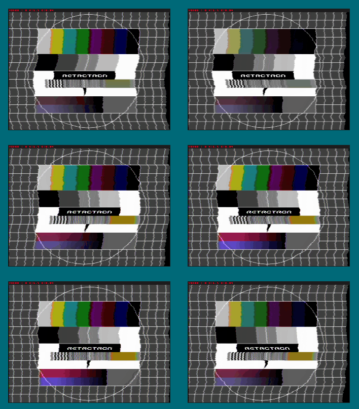
hsync-pulse, detector, and instability tests
2015-12-12: First (b/w) image produced by Retrotron

video signal coding: b/w video and (de-)sync features
.:: NG_Phys ::.
NG_Phys is going to be a custom build physics engine with special emphasis put on higher accuracy and on a much deeper degree of sophistication to yield that special something making our games feel different. Contrary to many common physics engine, which put emphasis on simulating "larger" worlds but with less accuracy or strong simplification of the physical model, the focus of our engine is more on "smaller" worlds" behaving more natural.
Sub-engines:
NG_Phys_Rigid (under development)
NG_Phys_CFD (under development)
NG_Phys_Soft
:: NG_Phys_Rigid ::
Equation of Motion
Fully non-linear six degrees of freedom equation of motion for computing highly realistic rigid body motion in three dimensional space and in realtime.
Implementation details
- variable mass (done)
- fully non-linear gyroscopic effects (done)
- variable center of mass (done)
- variable inertia tensor (done)
- rate of change of inertia tensor (done)
- principle axis of inertia (pending)
- aproximation of center of pressure (done)
- quaternion attitude (done)
- higher order integrators, rk4 / implicit / geometric (pending)
- rigid body attitude tracking (pending)
Snapshots
Note: The rockets are placeholder objects serving the development of the physics engine.
2013-08-22: Improved the integrator system
The integrator is now being able to integrate an n-dimensonal ordinary differential equation (ODE) which now leans itself to parallelization and to a much easier way of implementing new integration techniques, since the integrator now reduces to its most basic form.
For example, here is the inner-loop for the integrator of the entire 6-DOF system for integrating the linear- and angular momentum equations as well as the kinematic equation using a first order Euler scheme in this case;
// first order Euler step
for(int i = 0; i < dim; i++)
*y++ += *rhs++ * dt;
That's all! It can't get any easier. dim is the dimension of the entire system. rhs contains the state of the right-hand side of the ODE, i.e. y' = f(t,y), at time t, like forces, torques, etc. And y becomes the new state after doing an integration step. Implementing a higher-order Runge-Kutta scheme for example becomes way easy this way.
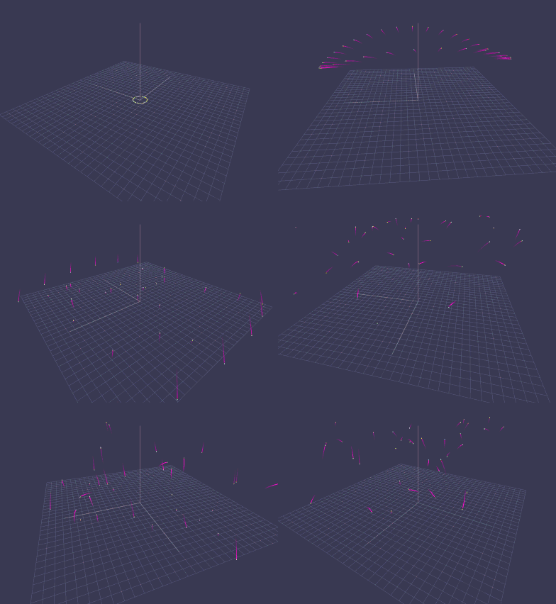
The intensity of a trail is modulated by the magnitude of the rocket's angular velocity. A more tumbling rocket will light up its trail a little stronger.
2013-08-16 : Improved tumbling
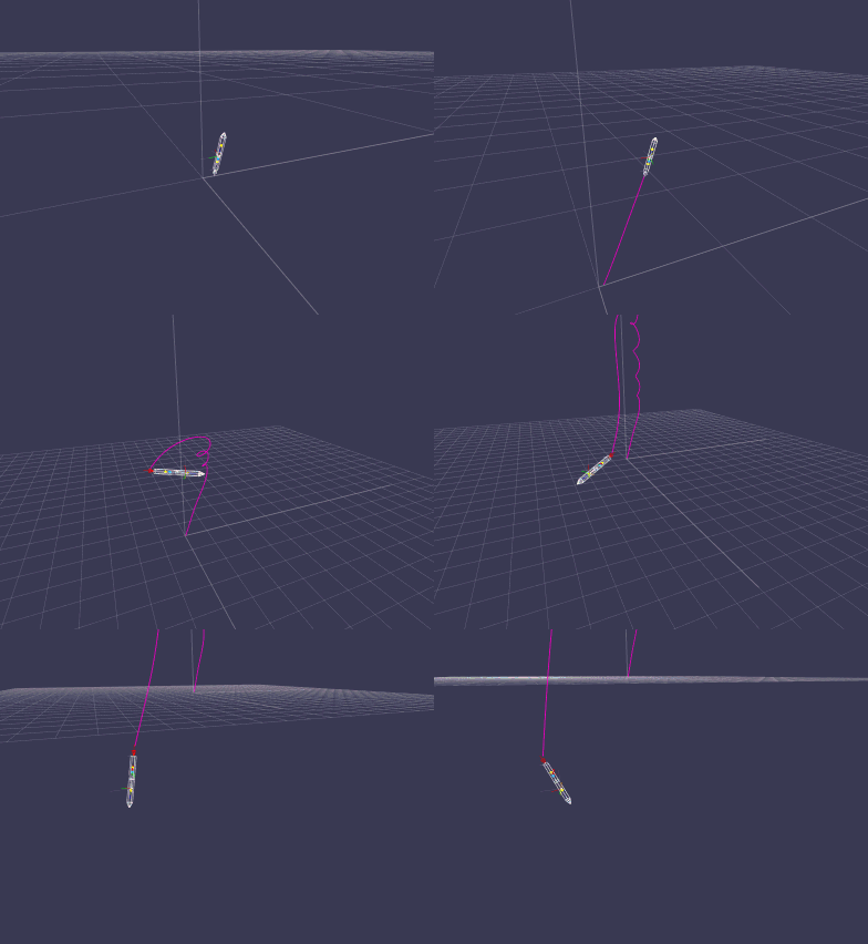
Rocket experiences a nozzel failure during ascend resulting in a tumbling motion.
2013-08-10 : For the show...
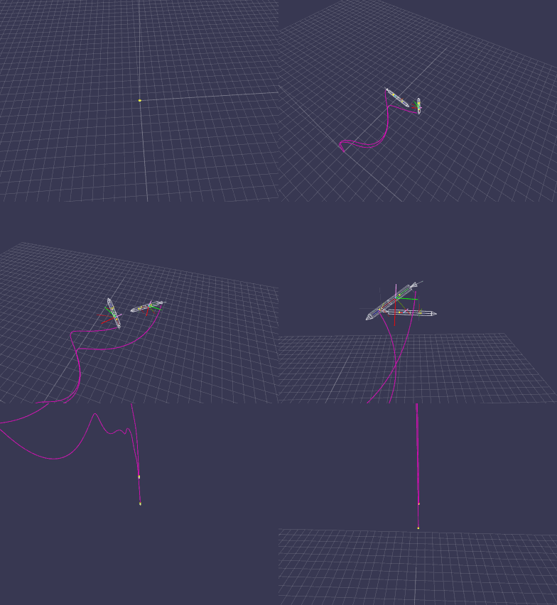
2013-08-09 : Rockets Under the Influence of Lift and Drag
In one of my previous post I have considered drag. But now I have finished the work on a lifting force model for rockets as well.
Computing the lift vector and lift force on a rocket wasn't so easy. Wings will be easier within this regard. Well, I didn't found any lift data for a rocket nor could I use the lift data from some wings straight. But from my knowledge about the behavior of the lifting force on some airfoils I have derived a lifting model for a rocket. It's sort of a full lifting model giving a lift coefficient over the entire sphere (any attitude of the rocket). This is way more advanced than general lift data for some airfoils, which are just two-dimensional in a given sense. That is to say, for an airfoil, using such 2d data is meaningless if the airfoil yaws around itself or the airfoil is traveling lateral with its wingtip being the, well, leading edge. This won't work. However, as long as the main air comes over the leading edge, one can use many of the known lift data for airfoils. However, I wanted to make the lift force for a rocket fully three-dimensional. Since this will give me those nice swirling patterns induced by the action of the lift- and drag force working in conjunction on the surface of a rocket while the rocket undergoes some strong changes in direction.
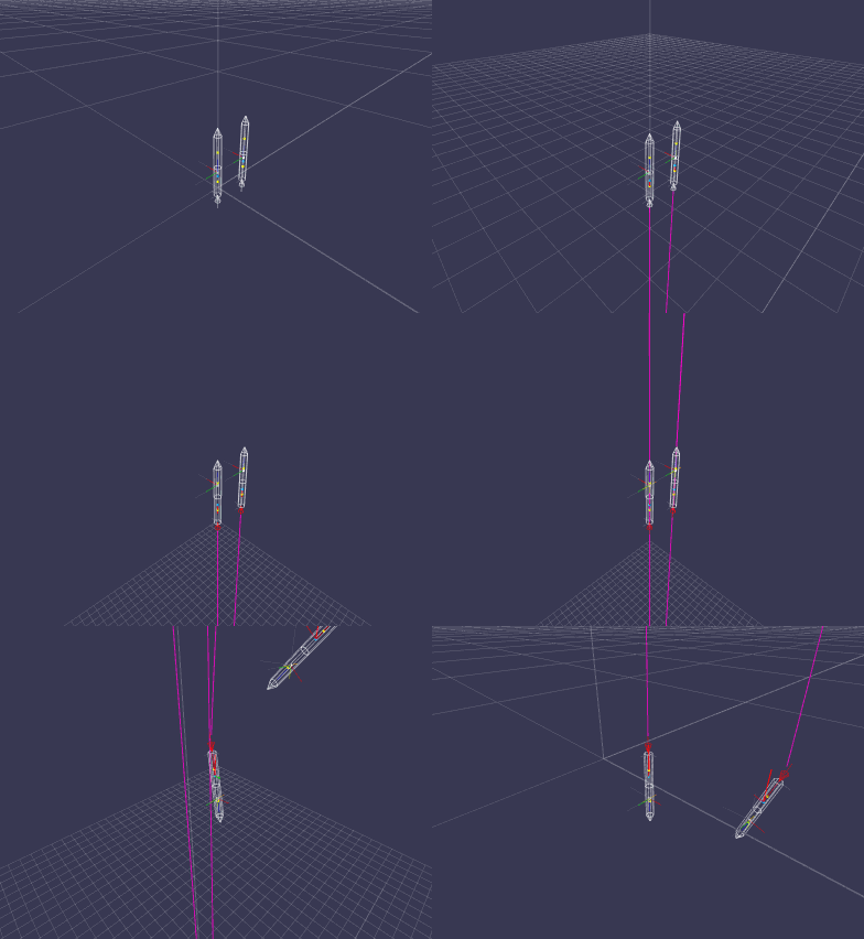
What we can see here are two rockets both pitched at 1/1000 degrees at lift-off. The rocket on the left will experience both lift (green) and drag (red) applied at the center of pressure (blue), while the one to the right will only experience drag. Upon reaching maximum height both rockets will start to fall. The rocket to the left turns over somewhat earlier because the lift force as well as the drag force are pushing on the rocket. But this lift force is missing on the rocket to the right, which turns over solely due to the drag force. One can also see that the lift force essentially stabilizes the rocket around its flight path faster than without it -- without any interaction from the outside (flight control).
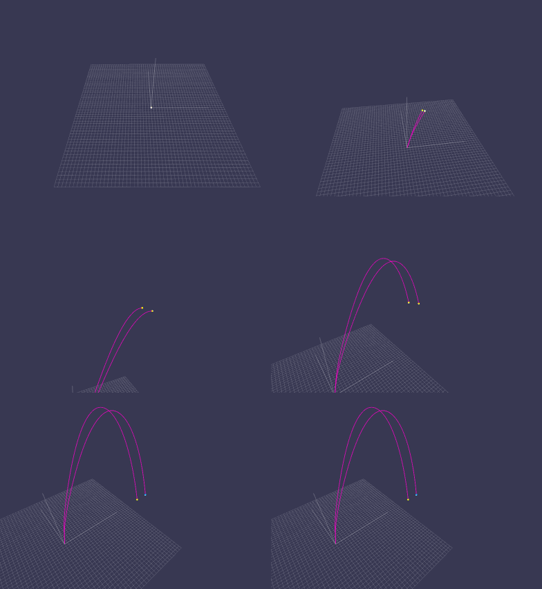
This animation shows the same rockets but now pitched at 6 degrees. One can see that the rocket with lift and drag rotates into a better angle leading to a longer distance of travel.
2013-08-04 : Approximation of the Center of Pressure
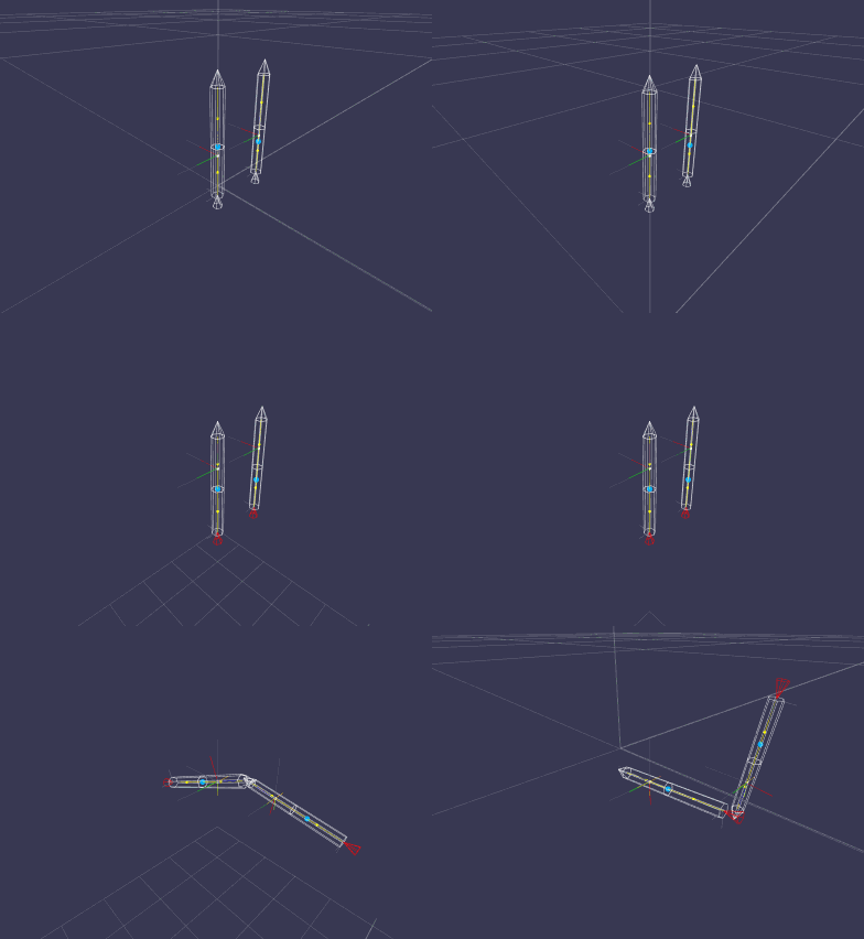
The rocket to the right has more surface area (fins not shown) attached to its lower stage pulling the center of pressure (blue) more downwards. At lift-off the rockets are pitched by 1/1000th degrees simulating sort of a disturbance. The pitch leads the rockets to be slightly unsymmetrical around their flight paths, respectively. Upon reaching maximum height both rockets have their center of pressure (blue) below the center of mass (small moving point slightly below and slightly above the center of pressure on each rocket at lift-off). After reaching maximum height, the rockets will start to descend due to gravity and will start to flip over due to the aerodynamic forces (lift and drag, drag only in this example) acting on the rockets. The point of action of these aerodynamical forces can be thought off as acting through the center of pressure. With respect to the given example here, the drag force pulls at the center of pressure while the rockets are descending at a slight angle. This, essentially, produces a torque around the center of mass leading the rockets to flip over. Note: The strong oscillatory motion will be damped by a lifting force, which isn't implemented yet. For the sake of completeness; the rocket do burn fuel out of the lower section and as such loses mass making the lower stage much lighter then the upper stage as one can see by the moving center of mass for each rocket. So it becomes way easy for the drag force to flip the lower stage over. The rocket to the right flips earlier due to the longer momentum arm the center of pressure makes with the center of mass.
2013-07-29 : A Drag Force Model for Rockets
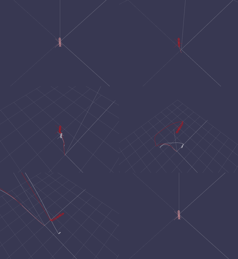
The white rocket experience drag whereas the red one doesn't. The drag force pulls on the center of mass only, hence, no rotation due to drag, yet. During ascend the rocket undergoes a nozzle failure producing a large angular momentum while the thruster still pushes at full throttle. A split second later the thruster is turn off.
2013-07-23 : Full Non-linear Linear- and Angular Momentum Equation Including Variable Mass
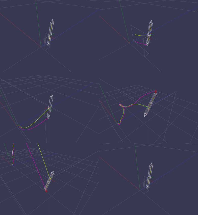
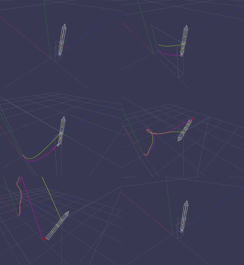
(slow motion)
2013-07-08 : Linear Momentum Equation + Variable Mass
The two figures below show a representaion of a rocket composed of two stages. The weight of the first stage (the one lowest to the ground) has two times the weight of the second stage and consist of about 90% of fuel. Once the thuster ignites, fuel burns at a given rate pushing the rocket upwards while at the same time reducing the weight of the first stage and as such the weight of the entire rocket. At burn-out time the nozzle's thrust direction, indicated at the tail end of the rocket, turns fully black and the center of mass of the rocket has shifted to the upper more heavier second stage of the rocket as it should be.
Figure 1, Figure 2
Constrains
Collision Detection and Collision Response
:: NG_Phys_CFD ::
We will start out with solving the three-dimensional Navier-Stokes equations on structured grids. This eases the implementation and keeps computational resources within bounds. With the insight gained we will later tackle the same problem on unstructured grids using the finite-element method and without any grid (meshless) using the finite-integral method allowing us to approximated curved objects much better while computing very interesting fluid flows around them.
The initial use of this engine is to generate some pleasing wind fields for some of our video games we have in development to give them a natural touch and to make their gameplay more challenging.
Implementation details
- time and space discretization / finite difference scheme (FDM) (pending)
- Gauss/Seidel/SOR iteration scheme (pending)
- boundary conditions (pending)
- Poisson solver (pending)
- resolvent solver (pending)
- characteristics (pending)
- general finite difference formula (pending)
- massless particle transport (pending)
- species transport (pending)
- thermal convection (pending)
- buoyancy (pending)
- obstacles (pending)
.:: NG_Math ::.
Sub-engines:
NG_Math_Linalg
NG_Math_Integral
NG_Math_Solver
NG_Math_ODE
NG_Math_PDE
NG_Math_FEE
:: NG_Math_FEE :: concept
The Finite Element Engine (FEE) is an investigation to build a flexible library to be used for computing solutions of partial differential equations for video games that can be expressed in the realm of the finite element, finite integral, and finite difference theory. At first instance, the use of FEE is thought of as a middleware tool to implement/model partial differential equations as well as fast mathematical and fast numerical approximation schemes. FEE will be developed in concert with its mathematical description, the {Architecture}; its implementation, the {Processor}; and its application, the {Library}. FEE should ease the implementation of partial differential equations and should make the power of such equations accessible to the video game programmer and designer to model, control, and simulate physical as well as non-physical worlds
.:: NG_Gfx ::.
Sub-engines
:: NG_Gfx_DCPU16 ::
Abstract
The NG_Gfx_DCPU16 engine is a computer graphics software package, under development, for generating and displaying interactive three-dimensional environments, pictures, and abstract art forms.
Introduction
The NG_Gfx_DCPU16 graphics engine's generic use is to be understood as an API (Application Programming Interface) to be used by programmers for building two and three-dimensional computer programs for the DCPU-16.
An intented use for the NG_Gfx_DCPU16 graphics engine is as follows:
- 3D API for the DCPU-16 (useful for video games coming with a build-in DCPU-16),
- Video game development
- Low-polygon art
- 3D editor/modeller
- Digital art form creations (ASCII shading/raytracing, color reproduction via halftoning
- Book (put on hold): "3D Graphics Programming for the DCPU-16" : The intented purpose of this book is to show step-by-step how three-dimensional computer graphics starts off from the ground without neglecting anything in-between and without relying on any external resources or libraries, by explaining in detail the intrinsic mathematical character necessary and by showing how to implement the fundamental graphics algorithms at the machine level using only the native instructions to give the reader an unrivaled understanding and a maximum insight into exactly how three-dimensional computer graphics comes to live.
Coding
In progress...
- quaternions
- procedural surface generation
- 3d stereoscopic rendering
- oblique linear and possibly some non-linear perspective projections
- multiple viewports
- proper camera model
- digital halftoning, dithering, patterning
- halftone/dither shader
- lighting model (flat shading for a 1-bit frame buffer)
- sub-pixel line rendering
- sub-pixel polygon rendering
- vector display output (SPED-3)
Demonstrations
ver: 0x2ede9ac93c

Procedural surface generation.
ver: 0x2ede7d2ebf

First run of a lighting model using halftone techniques to simulate shades with just one color on a 1-bit monochrome frame buffer.
ver: 0x2ed91e35d0

An edge-based polygon rasterizer, using a very solid and sound mathematical foundation based on a different approach using Taylor's formula for stepping the edges along without computing their slopes, was develop to fill arbitrary convex polygons without subdividing them into triangles. Due to its iterative nature, the rasterizer can also render very thin and even degenerated polygons without generating pathological rendering results. The edges are optimal, best approximation on the given raster, and the endpoints are matched exactly. This situation can only be improved with sub-pixel rendering.
ver: 0x2ed910f0d6
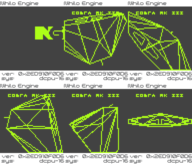
Cobra Mk III from the video game ELITE rendered with the Nihilo Engine.
ELITE & Cobra Mk III © Copyright 1984 Ian Bell & Braben
Releases
ver: 0x2ed910f0d6
This version implements 3D polygon clipping, which poses no restriction on the number of vertices used to define a polygon.

Engine characteristics:
ver: 0x2ed9004f09 +
- pol ygonal object definition
- 3D po lygon clipping
The animation shows 3D line clipping and 3D polygon clipping.
ver: 0x2ed9004f09
This is the first version that implements a minimum of 3D graphics algorithms.
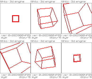
Engine characteristics:
- vertex/edge object definition
- matrix transformations
- perspective projection
- font rasterizer
- line rasterizer (new approach using Taylor's formula)
- 2D/3D line clipping
Display characteristics:
- video adapter: NYA ELEKTRISKA, LEM1802
- video mode: custom built text mode (hi-res)
- video resolution: 64x64, 1bpp, 1 color out of 16
- double buffering
Coding characteristics:
- language: DCPU-16 assembly, v1.7
16-bit fixed-point math

